![<?echo $_SERVER['SERVER_NAME'];?>](/template/twentyseventeen/skin/images/header.jpg)
For a decade, partial valve stroke testing for safety instrumented systems (SIS) has been a hot topic. The recently promulgated security standards have further led to discussions on this topic. However, it seems that few people understand the real reason for such tests. There are two main reasons for discussing the partial stroke test of the valve: one is to extend the manual test interval as much as possible; the other is to reduce the number of redundant hardware required for the higher safety integrity level (SIL). Like most things in life, it also comes down to one thing, which is cost savings.
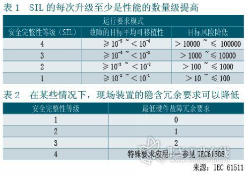
Safety system standards are based on performance and are not artificial. Essentially, the greater the level of process risk, the better the need for a better security system to control it. Table 1 lists the performance requirements for the four integrity levels specified by the standard.
There is no more way to reduce the failure rate of most field devices. First, the seller strives to provide high quality sensors and valves with the smallest possible number of components. In this way, the problem obviously stems from the bad application environment. The device malfunctions due to high temperature, corrosion, erosion, vibration, and other factors. Since devices used for safety instrumented systems (SIS) are usually stationary, not all faults can be displayed on their own, so all devices must be tested on a regular basis. (Except in very rare cases) Industry standards do not specify test frequencies. Test intervals are determined based on hardware failure rates and modes, redundancy levels, required performance levels (eg, SIL targets), and device quality.
Manual testing of valves, such as closing valves, typically requires shutting down the process. This is something that most factories naturally do not want to do. Doing this not only pays technical staff but it can also lead to danger. In addition, the cost of production downtime is often astonishing. If a branch is installed, the valve can be stroke tested online, but this leads to higher pipe costs, initial costs and additional procedures that must be monitored.
Diagnostic is critical The key to achieving a higher safety integrity level (SIL) with less hardware is to perform higher-level diagnostics. Many sensor manufacturers (such as ABB, Emerson, and Yokogawa) have SIL-2 class safety sensors. These devices provide a higher level of diagnostics than those of standard sensors. The provided diagnostics can detect potentially dangerous failures that may prevent the sensor from operating.
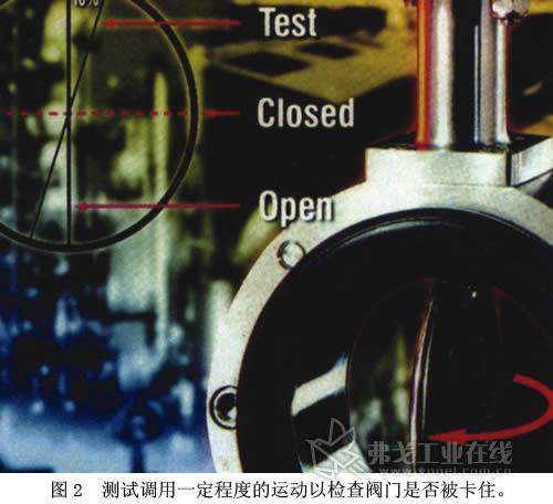
What kind of diagnostics are required for valves in safety applications? Most safety valves are permanently located in separate locations. The Pareto Principle (80/20 rule) and common experience have shown that most of the common failure modes of this type of valve are "stuck not work." You do not need to fully close the valve to determine if the valve is stuck; part of the stroke test is sufficient to detect most problems (Figures 1 and 2). With this type of test, a single valve can meet SIL-2 performance levels.
One approach is manual and is often referred to as "human intervention." This requires an operator to personally appear in front of the valve. Some manual methods require the insertion of special keys, while some end users design their own "home" solutions. .
The other way is automatic mode, so the operator does not need to stand next to the valve. These solutions typically require the specific hardware (valve, actuator, or positioner) and software (used to record and analyze valve performance) provided by the vendor. Other automation solutions work with the controller and the valve.
Safety Instrumented System (SIS) in conjunction with at least one hardware solution itself, and will be able to work with most existing valve together with the addition of only anti-limit switch or inductive detection device. This means no additional controller hardware or software is required.
Shut-off valve SIL detection criteria From a theoretical point of view, there is a linear relationship between the SIL and the erroneous command probability (PFD). Take the emergency stop valve as the research object.
From the conventional method, the emergency stop valve is tested using its full stroke test method for each inspection. 30 years ago, a test was performed every 2 to 3 years. With the improvement of mechanical properties and detection methods, a test is currently conducted in 5 to 6 years. The period of inspection and repair is reduced, so as to increase the production capacity of the factory, so the economic benefits are greatly improved. From the following analysis, we can see that the partial stroke test method can reduce the PFD value of the globe valve more than the full stroke.
PFD can be calculated by the following formula:
PFD=lD×TI/2
The PFD is linearly related to the proportionality coefficient lD and the test period. As the test cycle lengthens, the risk of PFD (False Instruction Probability) will increase further. The change of the proportional coefficient lD varies with the type, size, and operating environment, and usually takes a constant value of 3.04 x 10⁻⁶/h.
As the formula, with the extension of the detection period, the performance of the device itself will decrease. Many factories believe that the globe valve must be field tested. For on-site testing, it usually takes a full-stroke approach. However, the full stroke method can cause great damage to the valve seal. In particular, for soft seats, the frequent full stroke test seems to increase the valve safety factor, but the effect on the valve seal will create even greater problems for the valve to fail.
In addition to using the full stroke test method, another method is to use the bypass method for the valve test. However, the losses caused by this method should also be included in the PFD. The effect of this method on PFD will be more pronounced.
In contrast, the partial stroke method is used, that is, the valve is rotated by a small range of 15% (this range can be used to judge the ratio of valve failure). Its purpose is to reduce the frequency of the full stroke.
It can be seen from the formula that using the partial stroke method can further reduce the PFD:
PFD=0.7lD×TIPS/2+0.3lD×TIFS/2
TIPS: Partial Travel Cycle Interval TIFS: Full Travel Cycle Interval In process industrial field equipment, we can often see that many devices have PST (Partial Stroke Test) functions (some sites call this function a swim function). This function is mainly for the experimental detection function of the field equipment in a certain state, online maintenance process, without affecting the process production conditions. This function maximally detects the normality of the equipment and at the same time minimizes the possible impact of the inspection on the process. Its safety concept meets the SIL3 standard.
Partial stroke testing techniques to avoid improper application. In high-corrosion operation, partial stroke testing may result in increased wear, reduced shutoff capacity, and reduced valve life. A partial stroke test of a linear valve in a dirty environment will reduce the cleanliness of the stem by 20%, so the stem piston will be blocked by solids. When the valve is commanded to close, it may stop at only 20% of the stroke.
Test the sensing interval. There is no need to perform partial stroke tests on a daily basis, but if you do not perform partial stroke tests on a regular basis (at least once every quarter), you will not be able to achieve SIL-2 performance levels.
Understand the meaning behind the model. The benefits of partial stroke testing are based on data models. When the model is relatively simple (it is nothing more than a secondary-level algebraic equation), they rely on very subjective data that are difficult to verify (such as failure rate, failure mode, automatic diagnosis level, and changing the failure rate based on the frequency of use). However, the numbers will show how much influence various factors have, and which influences are negligible and which cannot be ignored.
Pay close attention to reducing the pressure on the actuator. When you are reducing the actuator pressure until the valve moves, note that when the actuator pressure drops to a considerable degree, the valve may stop and eventually close. If the valve still does not move after a period of time, stop the test.
Do not fall into the test results. Some solutions provide a lot of diagnostic information to detail the exact problem of the valve. When the valve cannot move to the specified distance within the specified time, other solutions simply report the "test failed" without specifying. In both cases, the end result is the same - the maintenance department must check the valve.
JAPANESE Vehicle Clutch Kit
Japanese Vehicle Clutch Kit range Toyota, Isuzu, Nissan, Mitsubishi, Suzuki, Mazda, Daihatsu, Honda. Most of them are applicable for passenger car and light commercial vehicle.
With over 20 years` experience of Clutch Cover, clutch disc and clutch kit assembly, you can rely on us to supply you with quality products, backed up by exceptional customer service.
OE No., SACHS No., LUK No., EXEDY No., AISIN No., VALEO No. are all available for us. It is our pleasure to be on service of you.
If you have any questions, please let me know and we will try our best to support the best price and great service.
I look forward to mutual development with you step by step.
Japanese Vehicles Clutch Kit,Toyota Clutch Kit,Isuzu Clutch Kit,Mazda Clutch Kit
Yuhuan Shouyuan Machinery Co., Ltd. , http://www.sycclutch.com