![<?echo $_SERVER['SERVER_NAME'];?>](/template/twentyseventeen/skin/images/header.jpg)
I. Overview
TKT is an energy conservation and environmental protection project and is an abbreviation for “Blast Furnace Gas Overpressure Energy Recovery Turbine Power Generation. The 2500m3 blast furnace TRT engineering computer control system of Baosteel Group No. 1 Steel Company (hereinafter referred to as No. 1 Steel Company) was designed by Wuhan Iron and Steel Design and Research Institute. At the beginning of design, the user put forward special requirements that are different from the conventional TRT control system:
(1) Using fieldbus control system FCS.
(2) Set up a TRT operation station in the main control room of the blast furnace so that the TRT workshop will be unattended during positive production.
After nearly six months of design, programming and debugging, the project was successfully put into production in March 2003.
Second, FCS system configuration
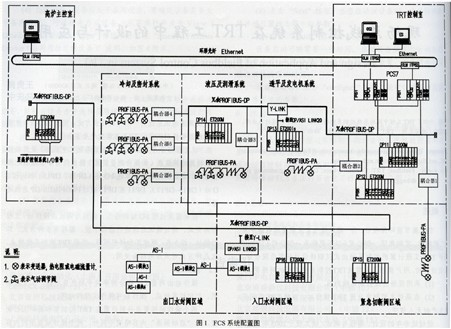
In the design of the TRT project of No. 1 Steel Company, the authors demand that the field bus technology not only be mature and reliable, but also be as redundant as possible to ensure that the construction of the TRT does not affect the production of the main blast furnace. Therefore, by comparing and screening a number of fieldbus control systems, it is determined that the Siemens PROFIBUS, AS-I field bus combination and corresponding instrumentation devices are used, and the control system adopts PCS7. The FCS hardware is mainly composed of the control station, the operation station, and the connection and the external communication total velvet. The specific configuration is shown in FIG. 1 .
2.1 Control Station
The control station includes a main CPU and seven extended I/O stations (DPll-DPl7). As required, the remote I/O station (DPl3-17) is distributed in the field and in the main control room of the blast furnace 600 meters away from the TRTT control room. The controller can realize sequential control, logic control and loop control, including logic operation, arithmetic operation, PID adjustment related to loop control, function generation and ramp generation, etc. There are more than 200 function blocks in total. In order to ensure the high reliability of the system, the controller CPU (AS 417-4H), communication module and high-speed communication bus are one-to-one redundant. The fast response and mutual switching time of the redundant CPU meet the normal production and security protection of the TRT. Claim.
This engineering part of the switch input/output equipment is complete with the process, no bus interface; special detection instrument (such as vibration measurement device) output is still 4~20mADC analog signal, so the design also uses the local I/O station (DPll, DPl2) And remote I/O stations (DPl3-DPl7). DPll to DPl7 are connected via the PROFIBUS-DP bus.
The configuration, programming and commissioning of the controller and remote I/O station are done by the operator station/engineering station and online downloading via the communication bus. There are many ways to program, namely function blocks, instruction lists, sequence diagrams, and ladder diagrams. According to the characteristics of the TRT control system, these methods can be combined flexibly.
2.2 Operator Station
The operator station consists of two 21" high resolution flat color displays, industrial controllers, printers, etc. The operator station can also be used as an engineer station. The two operator stations are respectively set in the TRT control room and the main furnace control room, except The contents of the two operating stations are exactly the same as the operating modes of the "Startup Screen". TRT control room operation station is mainly used for debugging. The monitoring software uses SIMATIC PCS7 OS V5.1, which works on the Windows NT platform. It monitors real-time process data collected from local and remote I/O stations, PROFIBUS PA and AS-I field bus systems through rich and complete simulation screens. , At the same time related to the process operation. In addition, through the programming and configuration of the operating station, the following main functions are also realized:
• Alarm function: The alarm log provided by the monitoring software records events, information, and alarm status in milliseconds, responds according to the alarm level, and classifies and archives or triggers related actions (such as printing) according to requirements.
Security function: The user management provided by the monitoring software allows the user to set multiple rights, set the corresponding encryption level for different operators, and record the operator's important operation process.
Data Management: The tag software and the tag editor provided by the monitoring software can record, display, print, and copy the historical trend values ​​of important parameters for data search and failure analysis.
2.3 Communication Bus
There are four types of communication buses, namely Industrial Ethernet, PROFIBUS-DP, PROFIBUS-PA and AS-I.
(1) Industrial Ethernet
It is used for the communication connection between the TRT operation station and the control station, the TRT operation station and the operation station of the main control room of the blast furnace. Ethernet is an open, high-speed, redundant structure with a communication speed of 10M/s. The communication between the two operating stations uses ring-shaped optical fiber and the distance is about 600m. Communication between operator station and control station adopts coaxial cable and corresponding communication card (CP443-1 et al. The ring fiber and coaxial cable use the connector OLMITP62. The operation station and the control station are set different addresses through software. Number to identify.
(2) PROFIBUS-DP
ROFIBUS-DP is divided into two types according to the function. They are respectively connected with the DP communication port on the main CPU and the main frame communication card (CP443-5). A communication connection between a TKT control station and local I/O stations (DPll, DPl2) and remote I/O stations (DPl3~DPl7) is a redundant structure; another is used for TRT control stations and Y - The communication connection between LINK, Y-LINK was previously a redundant structure, followed by a non-redundant PROFIBUS-PA coupler. Because the remote I/O station DPl3 is installed in a dangerous place with explosive gas, it is explosion-proof. Therefore, the PROFIBUS-DP connected to the I/O station is a non-redundant structure converted by Y-LINK. In addition, the connection with the AS-I device is also a non-redundant communication structure implemented by the Y-LNK and the coupler.
The control station accessing the local I/O station and the remote I/O station is identified by hardware setting different DP station numbers.
(3) PROFlBUS-PA
PROFIBUS-趴 is a special cable with a double-core shield structure. The signal is shared with the power supply, so it can provide work power for 2-wire PA meters. (For high-power meter devices with a PA bus interface, etc., an additional power supply is required.) PA meter is connected to PROFIBUS-DP through DP/PA-coupler and Y-LINK. Because PA meter's working power is also provided by DP/PA-Cooperator (each instrument is 24VDC, the average current consumption is l0mA), communication The speed is 31.25 Kbps, so the number of PA meters per coupler is greatly limited, although theoretically 32, but Siemens recommends about 10 units.
According to the distribution of on-site detection points and the settings of remote I/O stations, the design uses 6 PROFIBUS-PA buses and 3 pairs of Y-LINKs to implement communication between PA bus instruments and control stations. The Y-LINK settings are DPl2:1 pairs and DPl4:2 pairs, respectively. The Y-LINK station number setting and PROFIBUS-DP leveling are also accomplished through hardware dialing. The coupler produced by Siemens is transparent, ie the resolver does not have an address number and does not require any configuration of the Dealer. Therefore, different Y-LINK PA meter address numbers (within 0-126) are repeatable.
The PROFIBUS-PA bus is physically connected to the PA meter through a dedicated T-joint. A dedicated termination resistor must be connected at both ends of the PA bus to minimize signal reflection on the cable and improve transmission quality.
PA bus instrument measurement and control function configuration, parameter setting and status diagnosis are implemented by the PDM software installed in the engineering station; Y-LINK configuration is implemented by the PCS7 package software.
(4) AS-I
AS-I is the abbreviation of Actuator-sensor-Interface. It is a bus network used to bidirectionally exchange information between controller (master) and sensor/actuator (slave). It belongs to the underlying communication network system under the field bus (PROFIBUS, etc.). An AS-I bus system can be connected to various fieldbuses (eg FF, CAN-bus, etc.) via different types of gateways in the master station. AS-I bus can be used as:
1 A contact server of the fieldbus hangs a batch of slaves such as AS-I modules under the bus.
2 Communication with digital sensors (such as proximity switches, level switches, pressure switches, flow switches, etc.) and actuators (such as valves and audible and visual alarms) with AS-Interface.
3 Communicate with analog meters with AS-Interface and provide meter operating power.
Taking into account the project size and investment restrictions, the design uses 1 AS-T fieldbus architecture.
The AS-I host is DP/ASI LINK20. Both the host and power supply are installed in the cabinet (DPl6) shared with the inlet water seal valve area. The DP/AST TTNK2O uses non-redundant PROFIBUS-DP bus and turbine generator area cabinets. The remote I/O (DPl3) is connected and then connected to the main CPU of the TRT control room via the Y-LNK and communication module.
DP/ASI LINK20 and AS-I modules (slaves) use a special yellow 2-core flat repetitive punctured crimp cable to perform two-way signal communication; a special black flat repetitive puncture crimped cable is used to provide power for the module. The lengths of the signal cables of the host and the slave do not exceed 100m, and the number of slaves connected to a master station does not exceed 31.
The AS-I module is available in 2 channels, 4 channels, 8 channels, etc. The AS-I module is connected to the sensor using a dedicated cable with M12 connector. The cable connector protection class is IP67 to ensure that the module can be installed in the open air. Or place and work in harsh environments.
The AS-I bus equipment of this project includes 17 points such as digital input and output, analog input, etc. The design uses one AS-I signal line, one AS-T power line and one LINK20 host to realize AS-l and PROFIBUS. - DP communication, LINK20 hangs four AS-I modules, one of which is an analog input module that can supply power to 2-wire transmitters.
AS-I bus device measurement and control function configuration, parameter settings (including the communication address number) and status diagnostics are implemented by the handheld programming terminal; LINK20 configuration is implemented by the PCS7 package software.
Third, introduce the main control function that FCS realizes
TRT engineering control system is more complicated. In the FCS, the author researched and developed a new "integrated control function software", which realized the preparation control of the auxiliary system and the start-up of the host system without changing the original operating mode and operating habits of the blast furnace and ensuring the normal production of the blast furnace. Speed-up, grid-connected, power-up, furnace top pressure control and maximum power generation, TRT electric operation control during blast furnace air loss reduction, blast furnace anomaly or TKT system failure safety protection control. In addition to the auxiliary system requiring operator intervention during the start-up process, the start-up and shutdown of the host system as well as the operation control can be automatically implemented by the FCS.
3.1 Start up speed control
The start-up speed control is achieved by the FCS controlling the adjustable vane on the basis of canceling the starting valve. When the automatic starter is selected, the TRT automatically completes the control sections such as raising the rotation speed, casting excitation, boosting voltage, grid-connected power, and blast furnace top pressure, and the operator only needs to monitor the changed automatic control process.
In the process of automatic speed-up, the speed adjustment system will automatically generate the time-varying speed setting value according to the pre-stored speed-up curve and the change of the top pressure of the blast furnace, and continuously adjust the stator blade opening degree in conjunction with the rotation speed measurement value until the TRT and Net power generation.
3.2 liters of power control
After the TRT is connected to the grid, the power control system of the “Comprehensive Control Function Software†will automatically generate the power set value according to the pre-stored power curve and the change of the top pressure of the blast furnace to control the opening degree of the adjustable stator vane, and the whole power up process In addition, FCS also compares the power increase and the top pressure of the blast furnace in two adjustment processes. When the top pressure of the blast furnace fluctuates greatly, the power control pauses and the top pressure control system is activated; once the power rises to the preset value, That is automatically transferred to the top pressure control of the blast furnace.
3.3 Top pressure and normal power generation control
Top pressure control is also achieved by adjustable vanes. The pressure measurement value of the control loop is the same as the measurement value of the control loop of the original top pressure relief valve group of the blast furnace; and the pressure set value of the control loop is the control loop of the original top pressure relief valve group of the blast furnace. Fixed value obtained by "comprehensive control function software".
The steel company's TRT control system participates in the top pressure control during automatic start-up and automatic shutdown. The top pressure change caused by the TRT during pulling the gas from the starter and stopping the gas during shutdown is not more than 5 kPa. The top pressure control of the blast furnace realized by the “integrated control function software†at the moment of emergency shutdown and normal production of the TRT is better than the user's technical requirements.
TRT normal power generation control includes blast furnace top pressure control.
3.4 TRT Stop Control
The stop control implemented by the FCS system includes manual/automatic normal shutdown and emergency shutdown. The emergency stoppage runs through all control processes of the TRT.
(1) Normal shutdown
The normal manual shutdown is achieved by the virtual console of the FCS system. When the normal automatic stop is selected, the pressure regulation output of the top side of the TRT side is controlled and the adjustable static vane is slowly closed. Since the blast furnace top pressure regulating loop is always in the automatic control waiting state, the slow closing of the adjustable vane simultaneously makes the pressure reducing valve The group gradually opened.
TRTT automatic normal shutdown control is not only the top pressure control, but also the power reduction control. As the adjustable static blade is slowly turned off, the pressure reducing valve group is slowly opened. When the generator power reaches the decoupling value of the process requirements, Automatically send a signal to disconnect the generator to disconnect the power grid, and automatically close the emergency shut-off valve until the end of normal system shutdown.
(2) Emergency stop
Automatic emergency stop refers to a kind of safety protection control method implemented through "integrated control function software" installed in FCS. TRT automatic emergency stop conditions nearly 30, when there is any condition, FCS sends a signal to disconnect the generator and the grid, while the emergency shut-off valve, adjustable vane closed, bypass fast opening valve into the feedforward adjustment state. The feed-forward control system opens the bypass quick-open valve by a certain degree of opening, then enters the pressure regulation at the top of the furnace, and automatically flows the blast furnace gas from the TRT through the relief valve group. If the pressure relief valve is stuck, the top pressure of the bypass valve is fully adjusted until the valve group returns to normal; if the pressure relief valve is slowly opened, the bypass valve will ensure that the top pressure is stable. Under the premise of slow closing, realize the smooth transition between the TRT top pressure regulation system and the blast furnace top pressure regulation system under the emergency shutdown situation.
Emergency shutdown is a heavy-duty shutdown that takes less than two seconds to complete. Therefore, in addition to requiring the computer control system to respond quickly, it must have an accurate post-accident search function. The FCS records and prints out events in milliseconds, allowing users to easily find and analyze the cause of the first shutdown failure.
IV. Conclusion
The author puts forward several opinions on the design, installation, commissioning and application of this project:
(1) Although investing in FCS has increased the investment in the control system, the total cost of the cable (the total length of the signal cable for the project is less than 2,400 meters, and the total signal cable length of the conventional TRT control system is about 16,000 meters) and other materials and construction Installation costs are greatly reduced.
(2) Configuration and debugging Through the PDM software installed on the FCS engineering station, online PA bus instrumentation can be easily configured, downloaded and debugged. In addition to the on-site temperature transmitter, the PA bus meter can also set or initialize the address number through its own display window, which greatly saves the workload.
(3) Maintenance Through the PDM software, all information such as process parameters and diagnostic status of the on-site PA bus meter can be easily uploaded. Therefore, it is possible to adopt indoor maintenance methods and management modes of new on-site detection instruments and execution devices.
(4) When designing the PROFIBUS-PA bus, AS-T bus and bus instrument, the distribution of the fieldbus instrumentation equipment should be clear first, so that the number and installation of the DP/PA coupler and AS-T host can be correctly designed. Location, accurate calculation of the PROFIBUS-PA bus, AS-I bus cable length. In this respect, it is completely different from the conventional design.
In the production of TRT, the pressure regulation of furnace top achieved by FCS instead of the blast furnace control system is stable, and the power generation is around 800 OkW. It is estimated that the project investment can be recovered within two years, not only to recover a large amount of energy, but also to reduce the environmental pollution caused by noise. , For the user to obtain a very good economic benefits.As a model project of the company, also provided a good reference for the use of fieldbus control system for large stainless steel projects under construction at that time.
TKT is an energy conservation and environmental protection project and is an abbreviation for “Blast Furnace Gas Overpressure Energy Recovery Turbine Power Generation. The 2500m3 blast furnace TRT engineering computer control system of Baosteel Group No. 1 Steel Company (hereinafter referred to as No. 1 Steel Company) was designed by Wuhan Iron and Steel Design and Research Institute. At the beginning of design, the user put forward special requirements that are different from the conventional TRT control system:
(1) Using fieldbus control system FCS.
(2) Set up a TRT operation station in the main control room of the blast furnace so that the TRT workshop will be unattended during positive production.
After nearly six months of design, programming and debugging, the project was successfully put into production in March 2003.
Second, FCS system configuration
In the design of the TRT project of No. 1 Steel Company, the authors demand that the field bus technology not only be mature and reliable, but also be as redundant as possible to ensure that the construction of the TRT does not affect the production of the main blast furnace. Therefore, by comparing and screening a number of fieldbus control systems, it is determined that the Siemens PROFIBUS, AS-I field bus combination and corresponding instrumentation devices are used, and the control system adopts PCS7. The FCS hardware is mainly composed of the control station, the operation station, and the connection and the external communication total velvet. The specific configuration is shown in FIG. 1 .
2.1 Control Station
The control station includes a main CPU and seven extended I/O stations (DPll-DPl7). As required, the remote I/O station (DPl3-17) is distributed in the field and in the main control room of the blast furnace 600 meters away from the TRTT control room. The controller can realize sequential control, logic control and loop control, including logic operation, arithmetic operation, PID adjustment related to loop control, function generation and ramp generation, etc. There are more than 200 function blocks in total. In order to ensure the high reliability of the system, the controller CPU (AS 417-4H), communication module and high-speed communication bus are one-to-one redundant. The fast response and mutual switching time of the redundant CPU meet the normal production and security protection of the TRT. Claim.
This engineering part of the switch input/output equipment is complete with the process, no bus interface; special detection instrument (such as vibration measurement device) output is still 4~20mADC analog signal, so the design also uses the local I/O station (DPll, DPl2) And remote I/O stations (DPl3-DPl7). DPll to DPl7 are connected via the PROFIBUS-DP bus.
The configuration, programming and commissioning of the controller and remote I/O station are done by the operator station/engineering station and online downloading via the communication bus. There are many ways to program, namely function blocks, instruction lists, sequence diagrams, and ladder diagrams. According to the characteristics of the TRT control system, these methods can be combined flexibly.
2.2 Operator Station
The operator station consists of two 21" high resolution flat color displays, industrial controllers, printers, etc. The operator station can also be used as an engineer station. The two operator stations are respectively set in the TRT control room and the main furnace control room, except The contents of the two operating stations are exactly the same as the operating modes of the "Startup Screen". TRT control room operation station is mainly used for debugging. The monitoring software uses SIMATIC PCS7 OS V5.1, which works on the Windows NT platform. It monitors real-time process data collected from local and remote I/O stations, PROFIBUS PA and AS-I field bus systems through rich and complete simulation screens. , At the same time related to the process operation. In addition, through the programming and configuration of the operating station, the following main functions are also realized:
• Alarm function: The alarm log provided by the monitoring software records events, information, and alarm status in milliseconds, responds according to the alarm level, and classifies and archives or triggers related actions (such as printing) according to requirements.
Security function: The user management provided by the monitoring software allows the user to set multiple rights, set the corresponding encryption level for different operators, and record the operator's important operation process.
Data Management: The tag software and the tag editor provided by the monitoring software can record, display, print, and copy the historical trend values ​​of important parameters for data search and failure analysis.
2.3 Communication Bus
There are four types of communication buses, namely Industrial Ethernet, PROFIBUS-DP, PROFIBUS-PA and AS-I.
(1) Industrial Ethernet
It is used for the communication connection between the TRT operation station and the control station, the TRT operation station and the operation station of the main control room of the blast furnace. Ethernet is an open, high-speed, redundant structure with a communication speed of 10M/s. The communication between the two operating stations uses ring-shaped optical fiber and the distance is about 600m. Communication between operator station and control station adopts coaxial cable and corresponding communication card (CP443-1 et al. The ring fiber and coaxial cable use the connector OLMITP62. The operation station and the control station are set different addresses through software. Number to identify.
(2) PROFIBUS-DP
ROFIBUS-DP is divided into two types according to the function. They are respectively connected with the DP communication port on the main CPU and the main frame communication card (CP443-5). A communication connection between a TKT control station and local I/O stations (DPll, DPl2) and remote I/O stations (DPl3~DPl7) is a redundant structure; another is used for TRT control stations and Y - The communication connection between LINK, Y-LINK was previously a redundant structure, followed by a non-redundant PROFIBUS-PA coupler. Because the remote I/O station DPl3 is installed in a dangerous place with explosive gas, it is explosion-proof. Therefore, the PROFIBUS-DP connected to the I/O station is a non-redundant structure converted by Y-LINK. In addition, the connection with the AS-I device is also a non-redundant communication structure implemented by the Y-LNK and the coupler.
The control station accessing the local I/O station and the remote I/O station is identified by hardware setting different DP station numbers.
(3) PROFlBUS-PA
PROFIBUS-趴 is a special cable with a double-core shield structure. The signal is shared with the power supply, so it can provide work power for 2-wire PA meters. (For high-power meter devices with a PA bus interface, etc., an additional power supply is required.) PA meter is connected to PROFIBUS-DP through DP/PA-coupler and Y-LINK. Because PA meter's working power is also provided by DP/PA-Cooperator (each instrument is 24VDC, the average current consumption is l0mA), communication The speed is 31.25 Kbps, so the number of PA meters per coupler is greatly limited, although theoretically 32, but Siemens recommends about 10 units.
According to the distribution of on-site detection points and the settings of remote I/O stations, the design uses 6 PROFIBUS-PA buses and 3 pairs of Y-LINKs to implement communication between PA bus instruments and control stations. The Y-LINK settings are DPl2:1 pairs and DPl4:2 pairs, respectively. The Y-LINK station number setting and PROFIBUS-DP leveling are also accomplished through hardware dialing. The coupler produced by Siemens is transparent, ie the resolver does not have an address number and does not require any configuration of the Dealer. Therefore, different Y-LINK PA meter address numbers (within 0-126) are repeatable.
The PROFIBUS-PA bus is physically connected to the PA meter through a dedicated T-joint. A dedicated termination resistor must be connected at both ends of the PA bus to minimize signal reflection on the cable and improve transmission quality.
PA bus instrument measurement and control function configuration, parameter setting and status diagnosis are implemented by the PDM software installed in the engineering station; Y-LINK configuration is implemented by the PCS7 package software.
(4) AS-I
AS-I is the abbreviation of Actuator-sensor-Interface. It is a bus network used to bidirectionally exchange information between controller (master) and sensor/actuator (slave). It belongs to the underlying communication network system under the field bus (PROFIBUS, etc.). An AS-I bus system can be connected to various fieldbuses (eg FF, CAN-bus, etc.) via different types of gateways in the master station. AS-I bus can be used as:
1 A contact server of the fieldbus hangs a batch of slaves such as AS-I modules under the bus.
2 Communication with digital sensors (such as proximity switches, level switches, pressure switches, flow switches, etc.) and actuators (such as valves and audible and visual alarms) with AS-Interface.
3 Communicate with analog meters with AS-Interface and provide meter operating power.
Taking into account the project size and investment restrictions, the design uses 1 AS-T fieldbus architecture.
The AS-I host is DP/ASI LINK20. Both the host and power supply are installed in the cabinet (DPl6) shared with the inlet water seal valve area. The DP/AST TTNK2O uses non-redundant PROFIBUS-DP bus and turbine generator area cabinets. The remote I/O (DPl3) is connected and then connected to the main CPU of the TRT control room via the Y-LNK and communication module.
DP/ASI LINK20 and AS-I modules (slaves) use a special yellow 2-core flat repetitive punctured crimp cable to perform two-way signal communication; a special black flat repetitive puncture crimped cable is used to provide power for the module. The lengths of the signal cables of the host and the slave do not exceed 100m, and the number of slaves connected to a master station does not exceed 31.
The AS-I module is available in 2 channels, 4 channels, 8 channels, etc. The AS-I module is connected to the sensor using a dedicated cable with M12 connector. The cable connector protection class is IP67 to ensure that the module can be installed in the open air. Or place and work in harsh environments.
The AS-I bus equipment of this project includes 17 points such as digital input and output, analog input, etc. The design uses one AS-I signal line, one AS-T power line and one LINK20 host to realize AS-l and PROFIBUS. - DP communication, LINK20 hangs four AS-I modules, one of which is an analog input module that can supply power to 2-wire transmitters.
AS-I bus device measurement and control function configuration, parameter settings (including the communication address number) and status diagnostics are implemented by the handheld programming terminal; LINK20 configuration is implemented by the PCS7 package software.
Third, introduce the main control function that FCS realizes
TRT engineering control system is more complicated. In the FCS, the author researched and developed a new "integrated control function software", which realized the preparation control of the auxiliary system and the start-up of the host system without changing the original operating mode and operating habits of the blast furnace and ensuring the normal production of the blast furnace. Speed-up, grid-connected, power-up, furnace top pressure control and maximum power generation, TRT electric operation control during blast furnace air loss reduction, blast furnace anomaly or TKT system failure safety protection control. In addition to the auxiliary system requiring operator intervention during the start-up process, the start-up and shutdown of the host system as well as the operation control can be automatically implemented by the FCS.
3.1 Start up speed control
The start-up speed control is achieved by the FCS controlling the adjustable vane on the basis of canceling the starting valve. When the automatic starter is selected, the TRT automatically completes the control sections such as raising the rotation speed, casting excitation, boosting voltage, grid-connected power, and blast furnace top pressure, and the operator only needs to monitor the changed automatic control process.
In the process of automatic speed-up, the speed adjustment system will automatically generate the time-varying speed setting value according to the pre-stored speed-up curve and the change of the top pressure of the blast furnace, and continuously adjust the stator blade opening degree in conjunction with the rotation speed measurement value until the TRT and Net power generation.
3.2 liters of power control
After the TRT is connected to the grid, the power control system of the “Comprehensive Control Function Software†will automatically generate the power set value according to the pre-stored power curve and the change of the top pressure of the blast furnace to control the opening degree of the adjustable stator vane, and the whole power up process In addition, FCS also compares the power increase and the top pressure of the blast furnace in two adjustment processes. When the top pressure of the blast furnace fluctuates greatly, the power control pauses and the top pressure control system is activated; once the power rises to the preset value, That is automatically transferred to the top pressure control of the blast furnace.
3.3 Top pressure and normal power generation control
Top pressure control is also achieved by adjustable vanes. The pressure measurement value of the control loop is the same as the measurement value of the control loop of the original top pressure relief valve group of the blast furnace; and the pressure set value of the control loop is the control loop of the original top pressure relief valve group of the blast furnace. Fixed value obtained by "comprehensive control function software".
The steel company's TRT control system participates in the top pressure control during automatic start-up and automatic shutdown. The top pressure change caused by the TRT during pulling the gas from the starter and stopping the gas during shutdown is not more than 5 kPa. The top pressure control of the blast furnace realized by the “integrated control function software†at the moment of emergency shutdown and normal production of the TRT is better than the user's technical requirements.
TRT normal power generation control includes blast furnace top pressure control.
3.4 TRT Stop Control
The stop control implemented by the FCS system includes manual/automatic normal shutdown and emergency shutdown. The emergency stoppage runs through all control processes of the TRT.
(1) Normal shutdown
The normal manual shutdown is achieved by the virtual console of the FCS system. When the normal automatic stop is selected, the pressure regulation output of the top side of the TRT side is controlled and the adjustable static vane is slowly closed. Since the blast furnace top pressure regulating loop is always in the automatic control waiting state, the slow closing of the adjustable vane simultaneously makes the pressure reducing valve The group gradually opened.
TRTT automatic normal shutdown control is not only the top pressure control, but also the power reduction control. As the adjustable static blade is slowly turned off, the pressure reducing valve group is slowly opened. When the generator power reaches the decoupling value of the process requirements, Automatically send a signal to disconnect the generator to disconnect the power grid, and automatically close the emergency shut-off valve until the end of normal system shutdown.
(2) Emergency stop
Automatic emergency stop refers to a kind of safety protection control method implemented through "integrated control function software" installed in FCS. TRT automatic emergency stop conditions nearly 30, when there is any condition, FCS sends a signal to disconnect the generator and the grid, while the emergency shut-off valve, adjustable vane closed, bypass fast opening valve into the feedforward adjustment state. The feed-forward control system opens the bypass quick-open valve by a certain degree of opening, then enters the pressure regulation at the top of the furnace, and automatically flows the blast furnace gas from the TRT through the relief valve group. If the pressure relief valve is stuck, the top pressure of the bypass valve is fully adjusted until the valve group returns to normal; if the pressure relief valve is slowly opened, the bypass valve will ensure that the top pressure is stable. Under the premise of slow closing, realize the smooth transition between the TRT top pressure regulation system and the blast furnace top pressure regulation system under the emergency shutdown situation.
Emergency shutdown is a heavy-duty shutdown that takes less than two seconds to complete. Therefore, in addition to requiring the computer control system to respond quickly, it must have an accurate post-accident search function. The FCS records and prints out events in milliseconds, allowing users to easily find and analyze the cause of the first shutdown failure.
IV. Conclusion
The author puts forward several opinions on the design, installation, commissioning and application of this project:
(1) Although investing in FCS has increased the investment in the control system, the total cost of the cable (the total length of the signal cable for the project is less than 2,400 meters, and the total signal cable length of the conventional TRT control system is about 16,000 meters) and other materials and construction Installation costs are greatly reduced.
(2) Configuration and debugging Through the PDM software installed on the FCS engineering station, online PA bus instrumentation can be easily configured, downloaded and debugged. In addition to the on-site temperature transmitter, the PA bus meter can also set or initialize the address number through its own display window, which greatly saves the workload.
(3) Maintenance Through the PDM software, all information such as process parameters and diagnostic status of the on-site PA bus meter can be easily uploaded. Therefore, it is possible to adopt indoor maintenance methods and management modes of new on-site detection instruments and execution devices.
(4) When designing the PROFIBUS-PA bus, AS-T bus and bus instrument, the distribution of the fieldbus instrumentation equipment should be clear first, so that the number and installation of the DP/PA coupler and AS-T host can be correctly designed. Location, accurate calculation of the PROFIBUS-PA bus, AS-I bus cable length. In this respect, it is completely different from the conventional design.
In the production of TRT, the pressure regulation of furnace top achieved by FCS instead of the blast furnace control system is stable, and the power generation is around 800 OkW. It is estimated that the project investment can be recovered within two years, not only to recover a large amount of energy, but also to reduce the environmental pollution caused by noise. , For the user to obtain a very good economic benefits.As a model project of the company, also provided a good reference for the use of fieldbus control system for large stainless steel projects under construction at that time.
Corn Sheller,Hand Crank Corn Sheller,Maize Sheller,Large Capacity Maize Sheller
Shuangfeng Nongjiabao Machinery Technology Co., Ltd , http://www.starchmachine.nl